
The Effect of Leading Edge Slot Angle on NACA 2412 Airfoil’s Critical Angle of Attack
by Ian A. Ledford
Introduction
An aerodynamic stall occurs when the critical angle of attack is surpassed, producing insufficient lift for flight. They continue to be a significant, often disastrous problem in modern aviation. STAT Over the past few decades, several technologies have been developed in an effort to reduce the number of stalls that occur. On the leading edge of an airfoil, movable slats can both increase the camber of the airfoil and direct high pressure air towards the upper surface to delay boundary layer separation at higher angles of attack (AOA’s). Still, like most control surfaces, slats increase drag thus reducing efficiency so they are designed to retract. Unfortunately, these retracting systems add weight, potential for failure, and complexity in manufacturing.
Leading edge (fixed) slots apply the same principles as movable slats but cannot retract. Their simplicity solves the issues with slats outlined above, but they have no way of reducing the drag they create. This investigation will determine the best angle for a leading edge slot to improve an airfoil's lift at higher angles of attack, potentially delaying the onset of a stall.
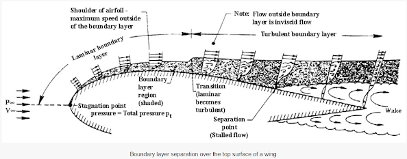
Figure 1: Annotated diagram illustrating fluid movement over an airfoil. Sourced from Aerospace Engineering Blog.
Theory
Fluid traveling closely to an object is subject to the no-slip condition (the fluid has zero velocity relative to the object) because of the high decelerating effects from its viscosity. Farther away from the
object, fluid travels in an inviscid flow. The boundary layer that forms between these two regions can be laminar or turbulent and plays a critical role in an airfoil's ability to generate lift.At the boundary layer separation point, the pressure gradient reverses, causing backflow in the form of a circular flow pattern and wake. All of these effects redistribute airflow over the remainder of the wing and can lower the total lift captured. Beyond the critical AOA, the boundary layer separates too soon to produce sufficient lift, resulting in an aerodynamic stall. For an airfoil, the adverse pressure gradient increases as the AOA increases. Principally, higher velocity airflow can temporarily overcome a higher pressure gradient thereby delaying the separation point. Leading edge slots and slats improve lift (and consequently increase the critical AOA) using the same principle. By creating openings in an airfoil, the higher pressure air underneath is allowed to flow upwards, which in turn accelerates according to Bernoulli's principle. As the higher pressure air flows down the concentration gradient it increases the energy of the air moving over the top of the wing, pushing the boundary layer separation point further back on the airfoil.
Experiment Setup
The Cessna 172 airfoil was selected for this experiment to represent low speed slot effects and because of its extensive presence in the aviation world. The airfoil was replicated by importing the Cessna 172’s four digit NACA code into Onshape (an open source computer aided-design program), cutting the slots through the airfoil, and extruding them to an appropriate spanwise length.
The slot widths were kept constant at 0.0125% of the chord length, inspired by a previous study conducted by the National Advisory Committee for Aeronautics airfoils on fixed slots. The study used a slot width of 2% of the chord length but it was decided to shrink that even more to further enhance the acceleration of air. It was theorized that the narrower slot would cause the air to accelerate more to maintain a constant volume flow rate. This would in turn, according to Benoulli’s principle, decrease the pressure and increase the air speed exiting over the upper surface of the airfoil. The surface area of the airfoils were kept constant at 193.5cm2 with an accepted error of 0.1cm2. The chord length and width was also constant at 8cm and 12cm respectively.
The Pitsco AirTech-40 wind tunnel, originally designed for model car testing, was used for this experiment. The tunnel records lift in grams using two scales located approximately 3.5 inches apart at the base of the test section. The tunnel also records drag in grams by using a “drag link.” With the tunnel not specifically being designed for airfoil testing, a mount was created to articulate each wing to a given AOA. Several methods were explored before a stepper motor was selected to position the airfoil to within the accuracy of a degree. Then, a cardboard base was constructed to support the stepper motor and airfoil in the center of the two lift scales. The base also provided an attachment point for the drag link. To allow airfoils to be securely fastened but still swapped quickly, a puzzle piece connection was 3D printed using OnShape. After printing, one part of the puzzle piece was glued to each airfoil while the other part was glued to the stepper motor. Finally, an arduino stepper code was sourced online and used to control the angle of the mount.
To record the data, the wind tunnel was turned on for 5 seconds before a photo was taken of the values displayed on the sensors. These values were then recorded in a notebook. Two trials were conducted within which each airfoil was tested at the following AOAs: 0°, 5°, 10°, 15°, 16°, 17°, 18°, 19°, 20°, 21°, 22°, 23°, 24°, and 25°. The tunnel's wind speed was also tested with a Kestrel 1000 Weather Meter. Lastly, testing was conducted on the mount to determine the lift and drag created. These findings were later subtracted from each airfoil's lift and drag data.
Results
The impact of a leading edge slot on a NACA 2412 airfoil’s lift generation is illustrated by figure 2. The data table was compiled by averaging the two trials conducted with the Pitsco AirTech-40 for each test airfoil. This data was compared with the lift captured by the NACA 2412 airfoil without a leading edge slot (the control).
Figure 2: Line graph illustrating lift performance data of each airfoil. Created using Microsoft PowerPoint.
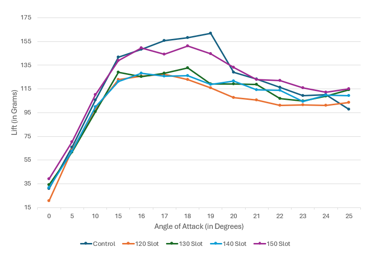
All the airfoils showed comparable levels of lift generation until approximately 15°, at which point the difference in lift produced by the airfoils exceeded 20 grams. All the airfoils with a leading edge slot produced more lift at an AOA of 25° than the airfoil that didn’t have one. With the exception of the airfoil with a leading edge slot positioned at 150°, the slotted airfoils failed to generate significantly more lift than the control at any other tested AOA. Figure 3 compares the lift produced by the airfoil with a leading edge slot positioned at 150° and the control.
Figure 3: Line graph with the lift performance data from the control airfoil and the test airfoil 150° angled slot. Created using Microsoft PowerPoint.
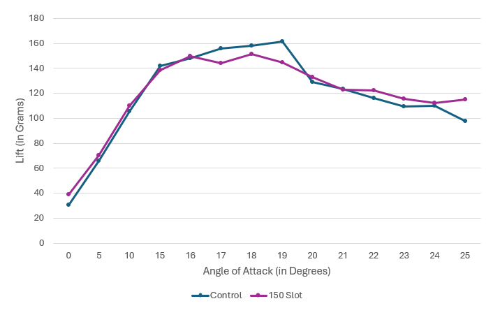
The airfoil with a leading edge slot positioned at 150° produced more lift from an AOA of 21° to 25° than the control. However, it generated a substantially lower amount of lift than the control from an AOA of 16° to 19°. The drag generated by each airfoil is illustrated in figure 4.
Figure 4: Line graph illustrating the drag performance data of each airfoil. Created using Microsoft PowerPoint.

The airfoils generated comparable drag until they passed an AOA of 19°. Between an AOA of 19° to 25°, the control airfoil produced much more drag than the slotted airfoils.
Analysis
The airfoils with a leading edge slot positioned at 120°, 130°, and 140° didn’t seem to offer a consistent improvement in lift. While they did produce more lift than the control at an AOA of 25°, they generated comparable or less lift than the control at every other tested AOA. The trend in the data clearly establishes these slot angles as ineffective in achieving the desired consistent increase in lift, particularly at higher angles of attack (15° through 25°). The airfoil with a leading edge slot positioned at 150° successfully increased the lift it generated at higher angles of attack when compared to the control. This slot position seemed to redirect a sufficient amount of fluid (air) at higher angles of attack to push the boundary layer separation point further back on the airfoil. With more laminar flow attached to the skin of the airfoil, it was able to generate more lift.
The leading edge slots behaved differently than initially predicted when it came to generating drag. They did not produce significantly more drag at any point than the control airfoil, instead universally decreasing the amount of drag generated past an AOA of 19°. Importantly, one of the primary stages of flight that leading edge slots have been observed to produce more drag occurs during cruise. It was not possible to recreate this environment due to the limitations of the wind tunnel that was available (the typical cruise speed for a Cessna 172 could not be reached).
The wind tunnel had several other limitations that must be considered when analyzing the data. The tunnel utilized for testing was located at Yorktown high school, and lacks any record of maintenance during its installation (15+ years). As a result, it must be assumed that there has been no maintenance conducted on the tunnel, leaving a risk that its sensors were incorrectly calibrated when the data was collected. Additionally, the wind tunnel's inability to transfer sensor readings onto a computer may have corrupted the data, as a crude photo method for data collection left a large margin for error. The drag data also has a potential for bias because the drag link was attached to the mount and not directly to the airfoil. Beyond the tunnel, limitations such as the permeability of the 3D printing filament could also have influenced the results.
Conclusion
This experiment had several limitations stemming primarily from the constraints on available resources; however, it also had several key successes. The collected data demonstrated that a NACA 2412 airfoil with a leading edge slot positioned at 150° could improve lift at higher AOAs. It can also be reasonably assumed that certain positions of leading edge slots can actually hinder the amount of lift a given airfoil is able to generate. Interestingly, slots appear to be a way to decrease drag, albeit at the expense of lift. These initial findings can be leveraged for further experimentation in a more controlled environment. The main limitation of this experiment was the precision with which it was able to be conducted with. Better wind tunnel equipment and material testing could eliminate this and may yield better results, presenting an opportunity for further analysis.
In short, this experiment’s findings provide a basis for further research, design, and prototyping. Based on the results of this experiment, specific leading edge slots seem capable of providing a viable solution to increase an airfoil's lift at higher AOAs, potentially also affecting its critical angle of attack.
[1] Tom Benson, ed., "Boundary Layer," National Aeronautics and Space Administration, accessed September 28, 2024, https://www.grc.nasa.gov/www/k-12/BGP/boundlay.html.
[2] Benson, "Boundary Layer," National Aeronautics and Space Administration.
[3] Holger Babinsky, "How Do Wings Work?," Physics Education 38, no. 6 (2003): [Page #], accessed September 28, 2024, https://doi.org/10.1088/0031-9120/38/6/001.
[4] Fred E. Weick and Joseph A. Shortal, "The effect of multiple fixed slots and a trailing-edge flap on the lift and drag of a Clark Y airfoil," NASA Technical Reports Server, [Page #], accessed September 28, 2024, https://ntrs.nasa.gov/citations/19930091501.
[5] "Arduino-Beginners-EN/E14-stepper-motor /stepper-motor-back-and-forward.ino," Github, last modified 2021, accessed September 28, 2024, https://github.com/BasOnTech/Arduino-Beginners-EN/blob/master/E14-stepper-motor/stepper-motor-back-and-forward.ino.
Bibliography
Aerospace Engineering Blog. Accessed September 28, 2024. https://aerospaceengineeringblog.com/boundary-layer-separation-and-pressure-drag/.
"Arduino-Beginners-EN/E14-stepper-motor /stepper-motor-back-and-forward.ino." Github. Last modified 2021. Accessed September 28, 2024. https://github.com/BasOnTech/Arduino-Beginners-EN/blob/master/E14-stepper-motor/stepper-motor-back-and-forward.ino.
Babinsky, Holger. "How Do Wings Work?" Physics Education 38, no. 6 (2003): 497-503. Accessed September 28, 2024. https://doi.org/10.1088/0031-9120/38/6/001.
Benson, Tom, ed. "Boundary Layer." National Aeronautics and Space Administration. Accessed September 28, 2024. https://www.grc.nasa.gov/www/k-12/BGP/boundlay.html.
Microsoft. Microsoft PowerPoint. https://www.microsoft.com/en-us/microsoft-365/powerpoint.
Weick, Fred E., and Joseph A. Shortal. "The effect of multiple fixed slots and a trailing-edge flap on the lift and drag of a Clark Y airfoil." NASA Technical Reports Server. Accessed September 28, 2024. https://ntrs.nasa.gov/citations/19930091501.
About the Author
Hi! My name is Ian Ledford. I am a senior and IB diploma candidate at Washington-Liberty High School in Arlington, Virginia. I am a curiosity driven learner, with a deep passion for engineering. I have always wanted to know the “how” and “why” behind everything that I see. This past summer, I had the unique opportunity to work with fellow highschoolers and the incredible Virginia Tech Thinkabit Lab team! When I was brainstorming research project ideas, my continual fascination with flight led me to discover, through preliminary research, leading edge slots. With relatively little information available on the web, I was particularly excited to experiment with a more novel airfoil modification. Over the course of the internship and through continual trial and error, I became proficient in Onshape CAD and 3D printing. Next year, I am excited to attend a university where I can continue to explore and cultivate my passion for engineering.
Ian A. Ledford (He/Him)
ian22ledford@gmail.com